Instrument panel support attachment
Moderators: GAHorn, Karl Towle, Bruce Fenstermacher
Instrument panel support attachment
I have a '52 C-170B. It is missing both instrument panel braces that tie the stationary instrument panel to the firewall. (These can be seen on pg. 36 of the IPC -- fig. 19-50, p/n 0513000-6). Could someone describe them? Are they 1/2" "U" channels? angles? Where do they attach at the firewall? I couldn't find any holes in my firewall that would correspond. Are they riveted to the top firewall angle, fig. 19-3&4? Any help would be appreciated.
Gary
Gary,
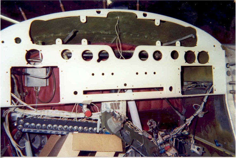
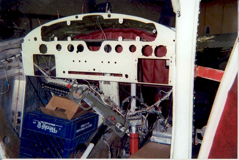
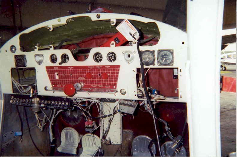
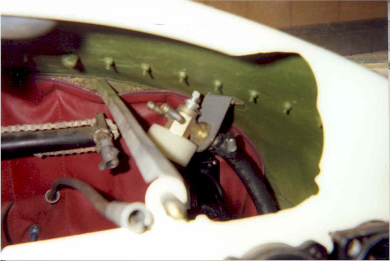
They are not a "U" channel, but rather a 90deg. angle with a tab that folds down at each end to provide an attach point.
Below are links to some photos from when I refurb.'d my '52 B. Hopefully they'll help.
http://www.damowry.com/images/projc170/panel01.jpg
http://www.damowry.com/images/projc170/panel02.jpg
http://www.damowry.com/images/projc170/004_NR.jpg
http://www.damowry.com/images/projc170/panel04.jpg
http://www.damowry.com/images/projc170/panel06.jpg
Last edited by doug8082a on Mon Oct 08, 2007 2:31 pm, edited 2 times in total.
Doug
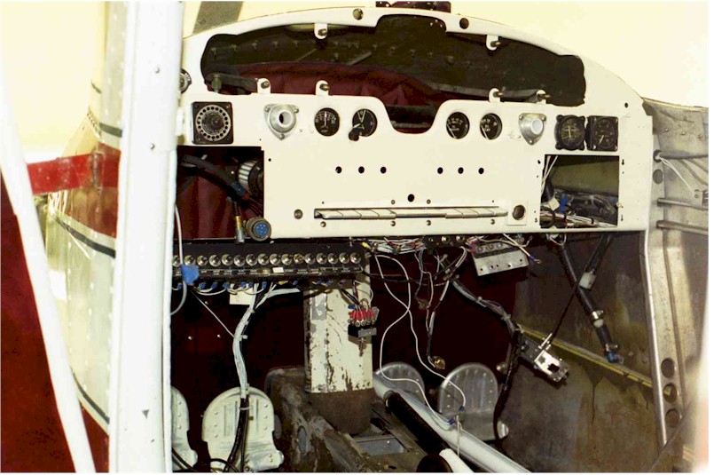
Doug,
Thanks for the quick reply. The last picture was especially helpful. It appears that your installation differed from the IPC. The brace in the picture attaches to the outboard tab on the panel whereas the IPC shows that it attaches to the inboard set of tabs. Edit: I think the brace attaches to the panel next to the control yoke ball. See fig. 38-6 in the 170B IPC.
Thanks for the quick reply. The last picture was especially helpful. It appears that your installation differed from the IPC. The brace in the picture attaches to the outboard tab on the panel whereas the IPC shows that it attaches to the inboard set of tabs. Edit: I think the brace attaches to the panel next to the control yoke ball. See fig. 38-6 in the 170B IPC.
- Screen Shot 2022-02-12 at 11.22.38 AM.png (11.28 KiB) Viewed 895 times
Gary